PANEL ANTENNA CONSTRUCTION
Panel antennas are well suited for UHF project where a wide bandwidth is required
with a wide beamwidth. Most of the antennas on mobile phone towers are panel antennas.
Panel antennas could easily be mistaken for being a complex piece of equipment, but the
truth is they are actually quite simple in design and construction. The most common design
is an array of dipoles all phased together. Hence the name "phased array". You will find
many examples of phased arrays around that do not have a panel cover. TV antennas are
some of the best examples. UHF TV phased arrays usually look like four bow ties one on
top of the other. You will also see VHF phased array TV antennas, especially where there
is a big hill behind the antenna. Phased arrays have an excellent F/B Ratio (Front to Back
Ratio) and so eliminate a lot of ghosting from reflected signals. This is a very desirable
quality in high speed data transmissions like 802.11b to reduce
multipath errors.
commercial radio & TV stations also use phased arrays because of their wide beamwidth.
You see will some excellent examples on the top of TV towers.
CONSTRUCTION
The design I have chosen for this project is nice and simple and with you new found skills
of circuit board design, you should find this antenna very easy to build. For the basic
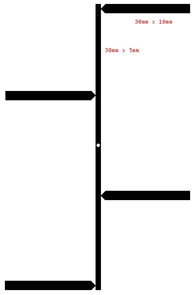
design start with a blank piece of double sided circuit board cut to a size of
65mm x 130mm. Then take 300mm long strip of electrical tape cut to 5mm wide and wrap it
around the board length ways so that the tape lines up in the center on both sides.
Then cut four lengths of eletrical tape 150mm long and 10mm wide and place them 30mm
apart so they form the four elements of the array. Make sure in both cases that the tape
lines up as close as possible on both sides of the board. When your done you will then need
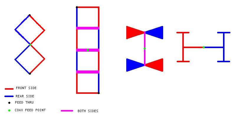
to cut the tape and remove one half element alternately on each side. The result should
look like this design on both sides of the board.
It is now ready to be etched. When you have finished you then need to dril a small hole
through the center of the board for the coax to be soldered to. Lightly countersink the
hole on one side to remove a little bit of the track to stop the core of the coax shorting
out. Solder the coax to the board so that the core is soldered to one side and the shield
to the other side. It doesn't matter what sort of coax you use in this case though it
should be 50 ohms impedance. I find the absolute best coax is semi-rigid because it is
small, there is no messy braid, it is relatively low loss at high frequencies and it
solders to the board very easily.
You will now need to mount your antenna onto a backplane. Jaycar sell a sheet of aluminium
that is perfect for the job, but you could also use another blank piece of circuit board.
The dimensions should be roughly 10% bigger than your elements. The backplane reflector
should be mounted 30mm behind the elements. Nylon screws and standoffs are the best thing
to use for small scale, but you could use metal standoffs and screws provided that they
support the driven board well away from the elements. An earth piece of metal near them
will de-tune them.
The next thing to do is protect the antenna so that it can be used outdoors. There are
several things you can do. The easiest is to 'tin' the copper tracks. This involves
coating them with solder using either a spray or just your soldering iron. This has
the effect of coating the copper with lead. Copper corodes much faster than lead.
You might choose to simply coat the copper board with clear or coloured contact.
This will certainly keep the water out and stop corrosion. You can also buy spray
on lacquer from Jaycar, it gives your board a professional glossy look. The most expensive
option is put it in a box. The plastic jiffy boxes from DSE and Jaycar are good for
the job and some even have aluminium lids that you can use as a backplane. I found a
large jiffy box at a ham radio field day which is big enough for the antenna and my
Access Point.
Finally you might care to do some true experimentation and work with some different
designs of phased array. Some examples are "Double Diamonds", "Quads", "Bow Ties",
"Collins H" to name a few.
You can also phase and stack the arrays for more gain.
An example is putting two panel antennas side by side and using a splitter. This may
sound difficult to do, but if you build two arrays onto one circuit board, then all you
need to do is add some extra tracks to phase it all together.
Building combiners and
dividers onto antenna circuit boards is not that much harder and will save you a few
dollars on additional connectors.