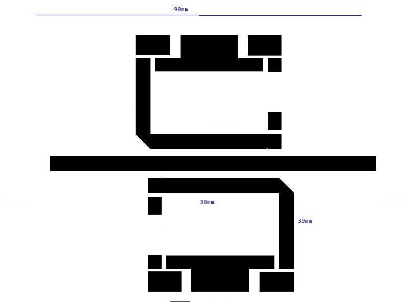
The other tracks on the board are for passive components and it isn't critical what size they are. The reverse side of the board will be ground, none of it is etched, so cover it with a sheet of contact to stop the acid eating it when you etch it. When you have finished etching the board it is ready for components. I would expect you to use panel mount N-Type female coax connectors, SMA or even BNC/TNC connectors if your trying to keep it cheap. Solder the conductor to the RF track and the shield to the ground plane on the other side of the board.
Next you will require two hot carrier schotky signal diodes. Again Jaycar and DSE sell them. The guy behind the counter won't have a clue in DSE, so use the catalogue to find the correct diode. You will also need two 1nF capacitors, two 47 ohm resistors, two 10K resistors, a 1K ohm potentiometer, a switch and the most sensitive Ammeter that you can get hold of. A microammeter (uA) is what you should be looking for.
Solder the two schotky diodes in place, make sure the black band on them is on the correct end (away from the RF). Then beside the diodes, solder in the 1nF capacitors and beside them solder the 10K resistors. At the other end of the sensor tracks solder the 47 ohm resistors. Remember that whenever you are soldering on an RF track to keep the leads as short as possible or use surface mount components if you can. Finally you must connect the back of the board to the front earth tracks. Drill small holes (yellow) in the board and solder a piece of wire through the hole so that both sides are connected. Now connect up the switch to the output of each diode and the meter and the 1K potentiometer and your ready to test it.
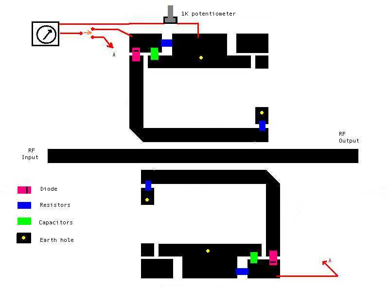
The diode is acting just like a crystal radio you may have built as a kid, only this one is working at 2.5GHz. The potentiometer adjusts the level to make it more useable. Since each side of the circuit only detects power traveling in one dirrection you need to have a switch to swap from the forward reference power to measure the reflected power on the other side of the circuit. Both sides are identical.
If you have ever used a CB SWR it's operation is exactly the same. Turn on your transmitter so that it
produces a single carrier. (your LAN card may not be able to do this and you will need to find another
signal source). Set the switch to forward power and adjust the level so that the meter is set to the highest
number on the scale and not hard up against the right hand wall. Then set the switch to reverse while the
transmitter is still running. The lower this reading, the better your antenna. I would expect that whatever
your meter has for it's highest value, that a good reading was anything below a third of that number.
example: 50uA maximum on the meter, then any reverse power less than ~20uA would be a good reading.